Tuesday, November 28, 2006

A Crash Course In Calibration

There are two parts to Calibration of your AV system - AUDIO and VIDEO. The following is a very simple explanation as the true nature of this topic far exceeds what could possibly be included in this BLOG.


Lets start with VIDEO.

Electronic Imaging Display Devices are based on the fact that we see in three primary colours - RED, GREEN and BLUE. Therefore every colour we see [both in the real world and on an electronic imaging displays] is made up of combinations of these three primary colours. The range that these colours appear on an electronic imaging device is called the GREY SCALE and it ranges from 0 to 255 [in PC values].


GREY SCALE

WHY GREY?

Simply put, equal amounts of RED, GREEN and BLUE equals GREY in VIDEO and the colour of GREY should be D6500K.

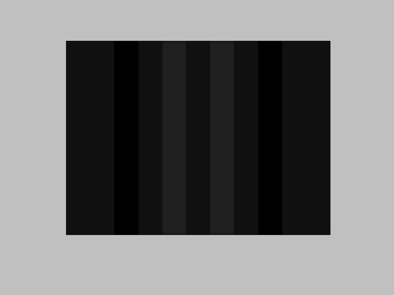
There are 11 shades of GREY in this "Reverse Ramps" pattern. The values here are in 10% increments where the very black [top left/bottom right] are RGB levels at PC 0. At the other end of the "Reverse Ramps" pattern is white at PC 255.

Video however does not extend to the full range of the signal, but is limited from "Video Black" [PC 16] to "Video White" [PC 235]. The range above white and below black is needed to prevent hard clipping of the video signal. Some sources [and or displays] can not display below PC 16 or above PC 235. If your source or display does clip the signal, it makes calibration more difficult than if you could see what is happening above WHITE and below BLACK.

SETTING BLACK LEVELS

A simple test to confirm if your system is clipping the video levels is to use a "PLUGE" test pattern. This pattern can be found on Joe Kane Productions - Digital Video Essentials or on a THX Optimiser found on many DVDs that are transfered by THX.


VIDEO BLACK TEST

On this pattern there are 3 shades of grey. The VIDEO BLACK background is PC 16, the BLACKER THAN BLACK stripes are PC 0 and the ABOVE BLACK stripes are PC 32. I choose 0 and 32 as it is easier to see than the normal 4% above and below video black. Basically what this pattern represents is black levels below and above VIDEO BLACK.

When setting your display's "BRIGHTNESS" or "BLACK LEVEL", you want to adjust the display's control so that the BLACKER THAN BLACK [PC 0] bars match the VIDEO BLACK [PC 16] background. You should still be able to see the ABOVE VIDEO BLACK [PC 32] bars.

SETTING WHITE LEVELS

The "RAMPS" pattern above is the easiest way to set modern video displays as you can see shades of grey BELOW and ABOVE VIDEO WHITE. White in video is PC 235, but there is no shade in these RAMPS pattern that is set to that level. What you need to see when you set the CONTRAST or PEAK WHITE level on your display is white at VIDEO WHITE and white ABOVE VIDEO WHITE. As mentioned above, some sources and displays clip the levels from PC 16 - PC 235, so you won't be able to see ABOVE WHITE or BELOW BLACK.

SETTING COLOUR

Given that equal amounts of RED GREEN BLUE equal GREY, means that unequal amounts provide all of the other colours...


COLOUR BARS

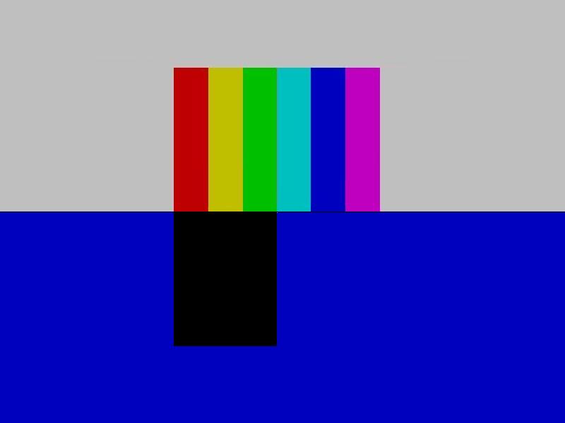
The image is divided in two and shows how the pattern would look both with [bottom half] and without [top half] the blue filter. Note that the RED YELLOW and GREEN now appear as BLACK. This is because they contain NO BLUE...

I created these COLOUR BARS on the PC at about 75% of their full range.

This pattern is comprised of -

PRIMARY COLOURS - RED GREEN BLUE

SECONDARY COLOURS - YELLOW CYAN MAGENTA

TERTIARY COLOUR - GREY.

If I had used the full PC 255 level, the GREY would actually be WHITE.

When setting COLOURS on your display, you should have at least a BLUE FILTER which is equal to WRATTEN 50. When viewing through the filter, the colours that contain BLUE will all appear the same once the setting is correct. So using a BLUE FILTER with a colour bar test pattern and you would see that the BLUE in the BLUE and the BLUE in the GREY matched. Also the BLUE in both the CYAN and MAGENTA also should match.

ADJUSTING TINT

comes in. Generally when using Sometimes the colours CYAN and MAGENTA don't match. This is where TINTPAL, we don't need to use TINT and in some cases, the display itself won't let you access to the TINT control. TINT shifts the colour bias between GREEN and MAGENTA.

SETTING SHARPNESS

SHARPNESS is a control that does not do what its name suggests. The SHARPNESS control is intended to increase detail, but what it actually does is add a white line to highlight dark parts of the picture. As a result it adds noise to the image as well as increases the CONTRAST. Whilst there is a propper patterns for the adjustment of SHARPNESS, it usually has no use in consumer display devices...

AUDIO ADJUSTMENTS...


SPL METERS

An SPL Meter is an invaluable tool as it will allow you to monitor the level of sound pressure from each speaker of your system. The following is brief, but is how your system should be calibrated but only applies to systems that have trims on ALL channels.

1. Set up the SPL Meter to the "75dB" position, select "C" and "slow". I use the digital meter on the right, so there is no 75dB setting and I also mount the meter on a tri-pod at the main seating location.

2. Turn the Master Volume to a "00dB" reference position. I use the actual 00dB position on my AVR which automatically winds up to that level from the previous listening level once the calibration mode is selected.

3. Activate the Internal Test Tone Generator of the sound system. My system automatically begins to output sound from the Left Speaker once it has reached the 00dB position.

4. Adjust the channel trims of each speaker in turn to read +75dB on the meter.

5. Adjust the SUB WOOFER to read 79dB on the meter. When using the Radio Shack Meter on the left, you will have to select the 80dB scale for this setting.

You are now Calibrated so that you can hear all of your motion picture soundtracks the way they were meant to be heard...

Mark


Inquiries

Back To The Top

Monday, November 06, 2006

C.I.H. Explained

There is something special about going to a cinema to watch a film presented in CinemaScope. The curtains open to reveal a wall to wall screen with an image much wider than conventional home video's HDTV 1.78:1 can achieve.

Previously the best we could do at home was to letterbox that "Scope" image. Thanks to modern home theatre [digital] projectors combined with an anamorphic lens, it is possible to project all images at a Constant Image Height, recreating that DELUXE WIDE SCREEN cinema experience in the home and preserving the true Aspect Ratio the way the director intended and allow Home Theatre users to enjoy CinemaScope at home.

When set up correctly, a Constant Image Height system will allow you to switch between different Aspect Ratios. This may be done electronically using a video scaler [either in the projector or an external video processor] or by removing the lens from the light path for the smaller Aspect Ratios of 1.85:1/1.78:1 [second image] or 1.33:1 [third image]. There is only 4% difference between 1.85:1 and 1.78:1.

2.37:1 FULL SCREEN "SCOPE" IMAGE

The C.I.H. system allows 100% of the projectors panel to display the "Scope" image at the full height of the screen with NO black bars top and bottom. Letter boxing only uses 75% of the vertical resolution for the image. The other 25% is wasted on the black bars to preserve the aspect ratio.

1.78:1 STANDARD WIDE SCREEN IMAGE
Standard Wide Screen like HDTV [1.78:1] and films with an aspect ratio of 1.85:1 will use the full height of the screen but the width will vary. The smaller image width is still very watchable because we are more sensitive to image height than image width.

1.33:1 IMAGE
Side pillars of unused screen will be seen when displaying smaller Aspect Ratios like the two images [1.78:1 and 1.33:1] above. Side masking may be employed to cover these areas of un-used screen to help create a more cinematic look.

SCALING + OPTICS = CORRECT GEOMETRY.

Constant Image Height is a 2 part process - "Scaling and Optics". Here is how it works.

LETTER BOXED "SCOPE" IMAGE
When a film's Aspect Ratio is "wider" than that of the display, the image height is reduced to fit in the width and still be able to maintain correct geometry. Normal "letter boxed" images [like the one above] waste precious vertical pixels on the black bars seen at the top and bottom of the image. This image is actually window boxed to show how a 16:9 letter boxed image would look when being projected onto a "Scope" screen.

ELECTRONICALLY SCALED IMAGE
PART ONE is the scaling or electronic reformatting of the image to use the full panel of the projector. The key to scaling for C.I.H. is to maintain the full width of image, but remove the black bars. As a result, the geometry is changed, making the image appear "tall and thin" as if "vertically stretched".

Full panel use has the potential to increase both the brightness and vertical resolution of the projected image. This can be done either with the projector [depending on the type of connection and source feed] or with an out board video processor. A 16:9 "enhanced" DVD is actually stored this way on the disc [in a 4 x 3 frame] so a "2.35:1" film will still have some black bars top and bottom that need to be removed. Blu-ray Disc offers 1920 x 1080 pixels and because they are not anamorphic, still contain black bars for Scope films.

OPTICALLY STRETCHED IMAGE

PART TWO is the optical stretching of the image to restore the image geometry. The anamorphic lens sits in the light path of the projector and optically stretches the light beam by a factor of 33% (1.33x for video and 2x for film) in the horizontal direction. This takes the 1.78:1 ratio or 16:9 display and Horizontally Expands it by 1.33:1x resulting in an image with an aspect ratio of 2.37:1. This process therefore restores the geometry of the electronically "scaled" image, resulting in a full height, but now much wider "scope" image.

SUBTITLE POSITIONING & CIH

Subtitles, [whilst not in every film], are often needed for us to understand what is being said [particularly in a foreign film] when the spoken language is not our native language like in this scene from D-WARS. Both shots are taken with the image scaled for CIH using the Letterbox mode on the projector. As can be seen in the 1st shot, only the first line of text remains after Scaling for CIH. The 2nd line of subtitles have been removed along with the black bars during the Scaling process.

CLIPPED SUBTITLES

To solve this problem, I now use a Phillips [BDP3000] Blu-ray Player because it is one of the select few BD players capable of shifting sub-titles for BD and DVD. DVD subtitles are generally stored as a bitmap which Blu-ray players seem to shift vertically by about 10% anyway.


REPOSITIONED SUBTITLES

In my opinion, video transfers should not be altered from what was seen at the cinema. The subtitles should remain in the active image where they appeared in the cinema release. Theatrically most subtitles will be a single line of text that extends across the width of the screen.

PRODUCTS - ANAMORPHIC LENSES & ADAPTORS

THE COMPLETE PACKAGE

The RUNCO CINEWIDE is probably the most expensive CIH solution, but is a total system comprising of everthing you need for CIH in your home including the purpose built DLP projector... If you already have a projector, there are quite a few anamorphic lens products on the market, some costing more than a projector itself. The prices range from just a few hundred to many thousands of dollars. There are basically two types - cylindrical [top image] and prismatic. The benefits of a cylindrical lens over a prismatic lens is that the cylindrical lens features adjustable optics allowing both horizontal and vertical lines to be brought into focus at the same time. Prismatic Lenses can not do this as their optics are fixed and not adjustable.


The New AUSSIEMORPHIC LENS MK5

In May 2011, I upgraded the MK4 to MK5 as the new cylindrcial lens to my line of products.

When the projector is fed a "scaled" signal from an anamorphically (16:9) enhanced DVD or Scaled Blu-ray Disc and projected through the lens on to a "Scope" screen, it produces a DELUXE WIDE SCREEN presentation with NO black bars top and bottom...

ANAMORPHIC VIDEO TEST PATTERN

When the LENS is properly aligned, the circles of this pattern should all appear "round" and you will have uniform focus from edge to edge.


Mark


Back To The Top